
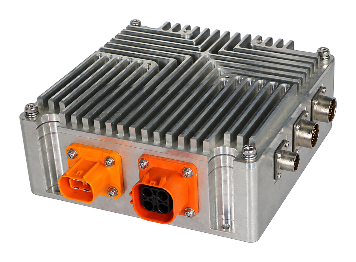
Motor Controllers

HL-M2005V

A high-voltage motor-control series with voltage, current and temperature monitoring and CAN communication.

HL-M2005V product image

Key parameters

Voltage

220 – 800 V

Peak current

25 A

Protection

IP65

Temperature

-40 – 85 ℃

Cooling

Aluminium-base natural cooling

Communication / I/O

7 optically isolated DI / 3 DO rated 2–3 A / one 5 V 0.3 A output / CAN

Dimensions

196 × 160 × 82 mm

Model matrix

ModelVoltagePeak currentRated current
HL-M2005V-220220 V25 A Peak value; see catalog for duty condition15 A
HL-M2005V-560560 V20 A Peak value; see catalog for duty condition10 A
HL-M2005V-800800 V15 A Peak value; see catalog for duty condition7 A

Features

  • Power-stage and thermal design for equipment integration.
  • Control functions selected around the motor, feedback device and duty cycle.
  • CAN and I/O configuration confirmed against the vehicle or equipment interface.

Typical application directions: Application suitability is confirmed against the selected model and project requirements.

Connectors & pin definitions

7 optically isolated DI / 3 DO rated 2–3 A / one 5 V 0.3 A output / CAN

HV bus connector · 2310540-1 · Mating part: 2310537-1; HV motor connector · HVSL364024A · Mating part: HVSL364064A103I; Sensor connector 1 · RT0W01419PNHEC03 · Mating part: RT0W61419SNHEC03; Sensor connector 2 · RT0W01419PWHEC03 · Mating part: RT0W61419SWHEC03; Supply / CAN connector · RT0W0106PNHEC03 · Mating part: RT0W6106SNHEC03

HV bus connector

Purpose
HV bus connector
Connector / terminal
2310540-1
Mating part
2310537-1
Applicable models
HL-M2005V-220 / HL-M2005V-560 / HL-M2005V-800
PinSignalFunctionElectrical parameters / notes
1HV bus positive2.5 mm² wire
2HV bus negative2.5 mm² wire
3Interlock signal wire 10.5 mm² wire
4Interlock signal wire 20.5 mm² wire

Source: product catalog, series starts on page 22
HV motor connector

Purpose
HV motor connector
Connector / terminal
HVSL364024A
Mating part
HVSL364064A103I
Applicable models
HL-M2005V-220 / HL-M2005V-560 / HL-M2005V-800
PinSignalFunctionElectrical parameters / notes
1Motor phase Wx2.5 mm² wire
2Motor phase V2.5 mm² wire
3HV negative2.5 mm² wire
4Motor phase U2.5 mm² wire

Source: product catalog, series starts on page 22

Sensor connector 1

Purpose
Sensor connector 1
Connector / terminal
RT0W01419PNHEC03
Mating part
RT0W61419SNHEC03
Applicable models
HL-M2005V-220 / HL-M2005V-560 / HL-M2005V-800
PinSignalFunctionElectrical parameters / notes
1GND
25V supply output40m A output capacity
3Encoder A+( or HALL-A+)A signal
4Encoder A-( or HALL-A-)
5Encoder B+( or HALL-B+)B signal
6Encoder B-( or HALL-B-)
7Encoder Z+( or HALL-C+)C signal
8Encoder Z-( or HALL-C-)
9Encoder Z+( or Z)ZEncoder error signal
10Encoder Z-
11SCK-SPI clock-
12SCK+SPI clock+
13MOSI-SPI MOSI-
14MOSI+SPI MOSI+
15Analog inputSupports voltage and current types
16MISO-SPI MISO-
17Ground
18MISO+SPI MISO+
19NC

Source: product catalog, series starts on page 22

Sensor connector 2

Purpose
Sensor connector 2
Connector / terminal
RT0W01419PWHEC03
Mating part
RT0W61419SWHEC03
Applicable models
HL-M2005V-220 / HL-M2005V-560 / HL-M2005V-800
PinSignalFunctionElectrical parameters / notes
15V supply output40m A output capacity
2GND
3Encoder E+( or E)
4Encoder E-
5Temperature sensor digital input 2 (ground)Ground terminal
6Temperature sensor digital input 1
7Motor temperature sensor 1-2Ground terminal
8multiplexed with -Motor temperature sensor 3-2 Chip select signal CS-Ground terminal Sensor SPI chip select
9multiplexed with -Motor temperature sensor 2-2 Chip select signal CS+Ground terminal Sensor SPI chip select
10DO output
11Motor temperature sensor 1-1
12Motor temperature sensor 2-1
13Motor temperature sensor 3-1
14Encoder A+(A)
15Encoder A-
16Encoder B+(B)
17Encoder B-
18Encoder Z+(Z)
19Encoder Z-

Source: product catalog, series starts on page 22

Supply / CAN connector

Purpose
Supply / CAN connector
Connector / terminal
RT0W0106PNHEC03
Mating part
RT0W6106SNHEC03
Applicable models
HL-M2005V-220 / HL-M2005V-560 / HL-M2005V-800
PinSignalFunctionElectrical parameters / notes
1CAN-H
2CAN-L
3Digital input
4Operating supply positive
5Operating supply negative
6Enable input

Source: product catalog, series starts on page 22

Wiring

  • The vehicle low-voltage supply powers control signals.

    Applicable models: HL-M2005V-220 / HL-M2005V-560 / HL-M2005V-800 · Catalog series starts on page 22

Dimensions & mounting

  • Overall dimensions: Length 196, Width 160, Height 82

    Applicable models: HL-M2005V-220 / HL-M2005V-560 / HL-M2005V-800 · Catalog series starts on page 22
  • Mounting hole spacing: Length 182, Width 146

    Applicable models: HL-M2005V-220 / HL-M2005V-560 / HL-M2005V-800 · Catalog series starts on page 22

Diagnostics & notes

  • Fault diagnosis, monitoring and protection functions support system reliability.

    Applicable models: HL-M2005V-220 / HL-M2005V-560 / HL-M2005V-800 · Catalog series starts on page 22

Documents

Use the full catalog for offline reference and archiving.

Start a conversation

Confirm the match against the equipment duty cycle

Vehicle and actuator conditions differ. Confirm the selection range against the actual project requirements.

Contact us