 HeliControl
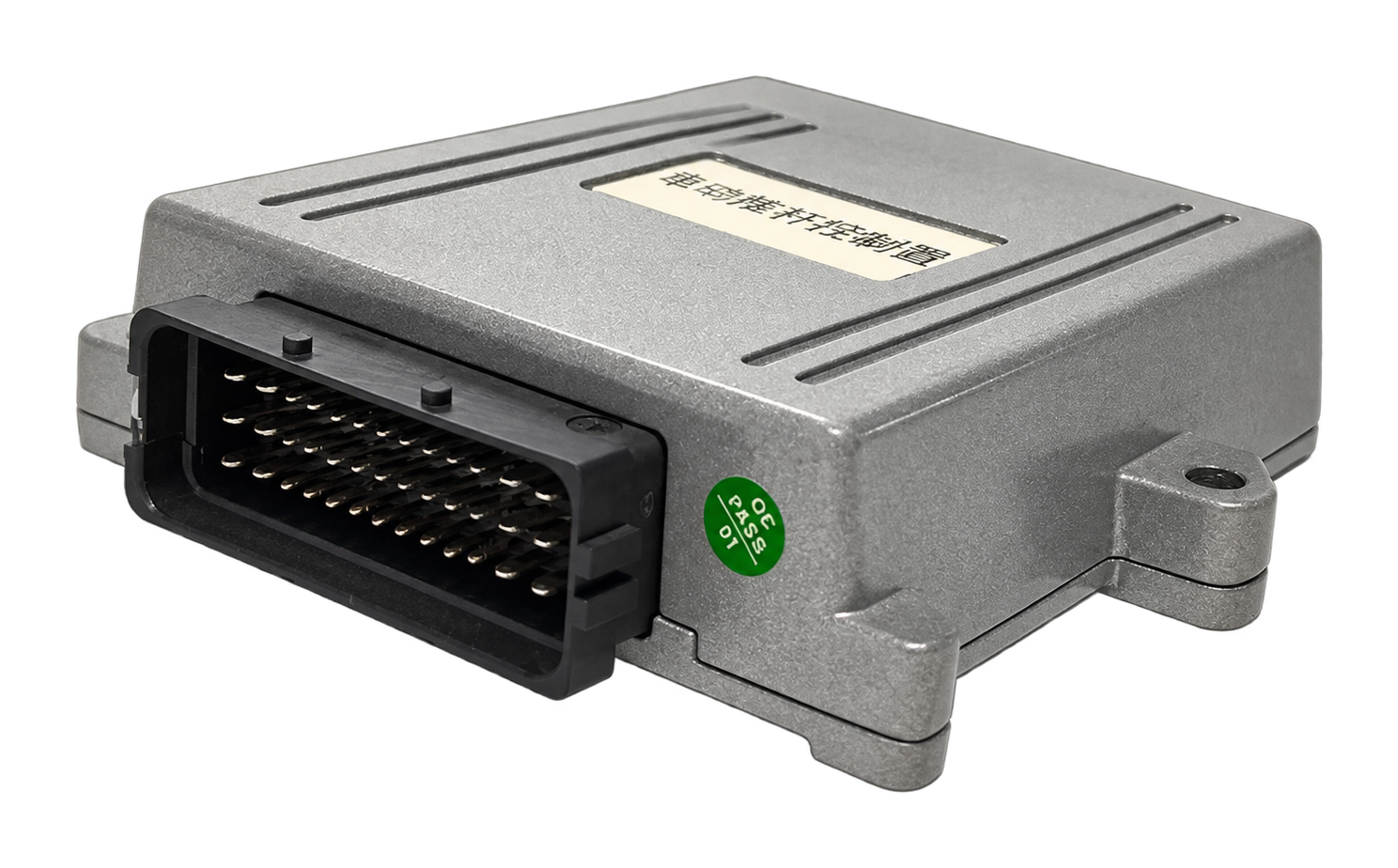
Control / motor connector
- Purpose
- Control / motor connector
- Applicable models
- HL-C2039
| Pin | Signal | Function | Electrical parameters / notes |
|---|---|---|---|
| 1 | MOTOR1 | Motor 1 output | |
| 2 | MOTOR2 | Motor 2 output | |
| 3 | AN14_IN | Analog 14 input | |
| 4 | BRK_OUT | Brake output | |
| 5 | BRK_OUT | Brake output | |
| 6 | BRK_OUT | Brake output | |
| 7 | CAN2_H | CAN2 high | |
| 8 | POW_EN | Controller enable | |
| 9 | D02_IN | Digital input 2 | |
| 10 | D03_IN | Digital input 3 | |
| 11 | CAN1_H | CAN1 high | |
| 12 | 48V+ | 48V positive | |
| 13 | 48V- | 48V negative | |
| 14 | MOTOR1 | Motor 1 | |
| 15 | MOTOR2 | Motor 2 | |
| 16 | AN12_IN | Analog 12 input | |
| 17 | AN13_IN | Analog 13 input | |
| 18 | AN16_IN | Analog 16 input | |
| 19 | AN15_IN | Analog 15 input | |
| 20 | CAN2_L | CAN2 low | |
| 21 | D01_IN | Digital input 1 | |
| 22 | AN2_IN | Analog input 2 | |
| 23 | AN1_IN | Analog input 1 | |
| 24 | CAN1_L | CAN1 low | |
| 25 | 48V+ | 48V positive | |
| 26 | 48V- | 48V negative | |
| 27 | MOTOR1 | Motor 1 | |
| 28 | MOTOR2 | Motor 2 | |
| 29 | AN11_IN | Analog input 11 | |
| 30 | AN10_IN | Analog input 10 | |
| 31 | AN9_IN | Analog input 9 | |
| 32 | AN7_IN | Analog input 7 | |
| 33 | AN8_IN | Analog input 8 | |
| 34 | AN5_IN | Analog input 5 | |
| 35 | AN6_IN | Analog input 6 | |
| 36 | AN3_IN | Analog input 3 | |
| 37 | AN4_IN | Analog input 4 | |
| 38 | 48V+ | 48V positive | |
| 39 | 48V- | 48V negative |
Source: product catalog, series starts on page 38